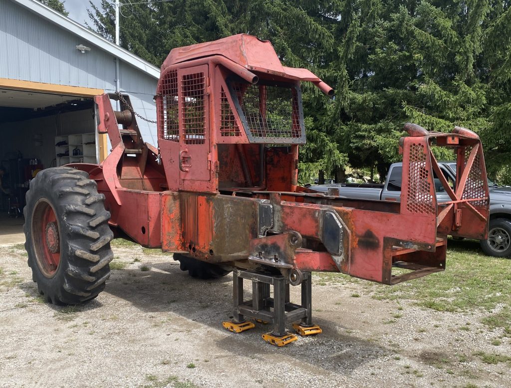
Recently we have received a badly damaged Timberjack skidder with multiple cracks in the front end. The damages have caused almost completed separation of the front end from the rest of the machine. In fact, after a complete analysis of the cracks we have concluded that the front of the frame has been hold by about 2″ of solid metal. In this article you will learn:
We have followed procedures in heavy equipment repairs in this Timberjack project
Call us, text us or email us for traditional and advanced welding services on your heavy construction equipment, heavy forestry equipment, heavy farm equipment and other heavy equipment. And leave us your feedback on our google profile. If you have some doubts regarding our welding capabilities please visit our product weldment page.
The minor cracks welding on heavy machinery, heavy equipment, and heavy construction machinery are possible in place or in owner’s shop within our mobile welding service. Therefore, we can weld repair all minor cracks within one day in the radius of about 200 km from London, Ontario. However, we prefer to bring all damaged machinery or heavy equipment to our shop in Lucan for projects involving complex welding or 2 days simple welding.
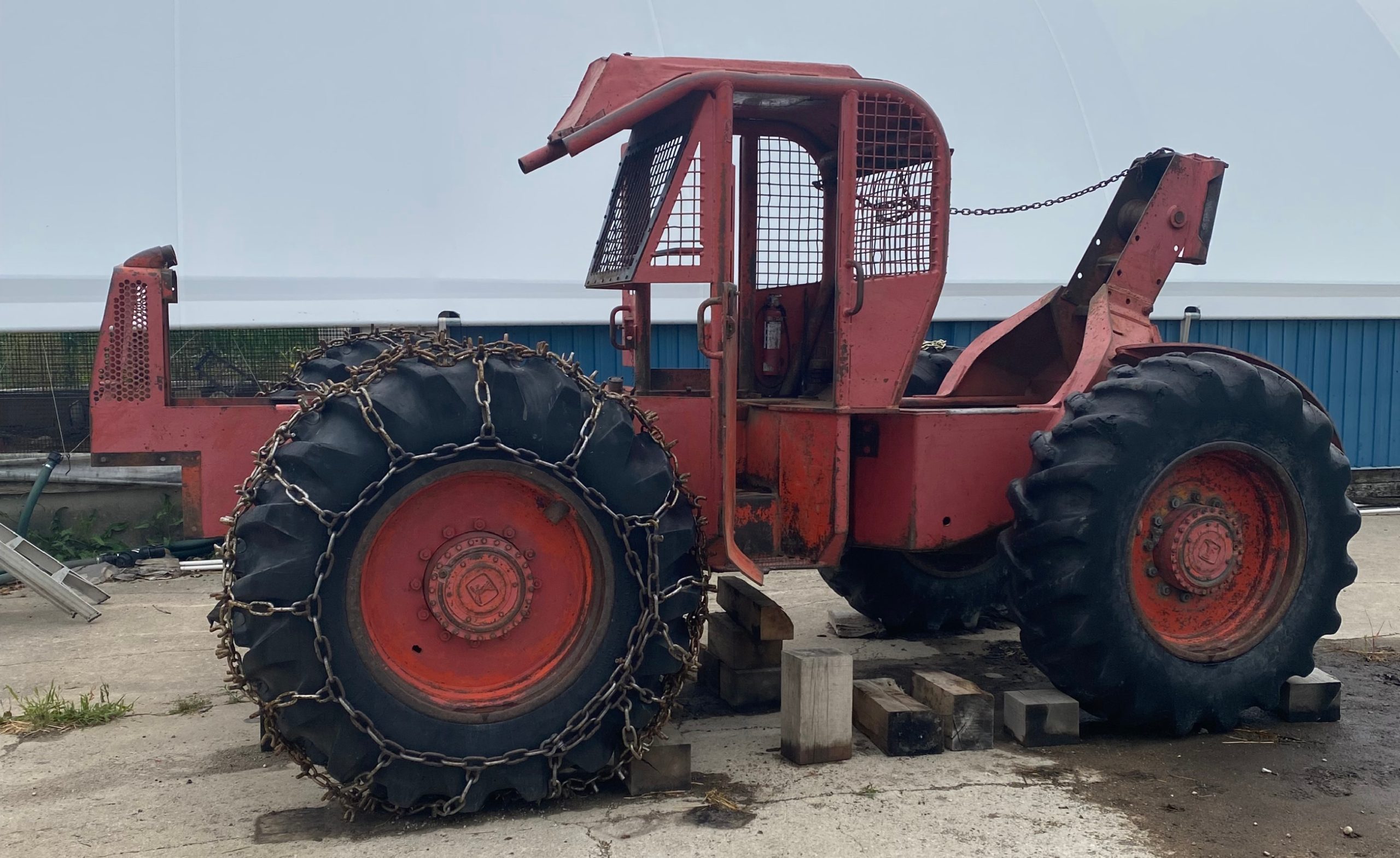
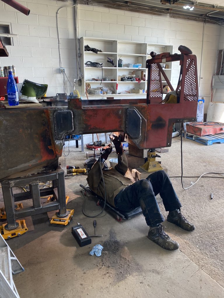
This Timberjack skidder, Model # 240 HSEAX was definitely a case of very complex welding but since we specialize in welding heavy equipment including cranes, we knew we will not disappoint our customer. Therefore we have decided to haul it to our shop where we can handle complex welding repair.
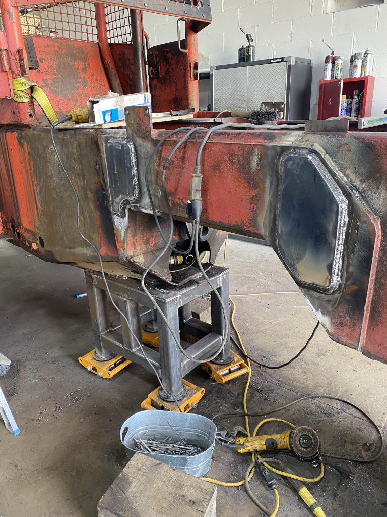
Since the cracks in front of the machine were very extensive, there was a possibility during loading for the front end to completely separate from the rest of the machine. In the worse case scenario, the front axle would have been attached to the rest of the machine only by a walking beam that has been cracked too. We definitely did not want this to happen. Therefore we have decided to remove the front axle and place this Timberjack skidder on a dolly. We have fabricated the dolly to sustain the weight of this skidder and any additional impact during loading. Then we have welded the dolly to the heavy plates at the bottom of the machine.
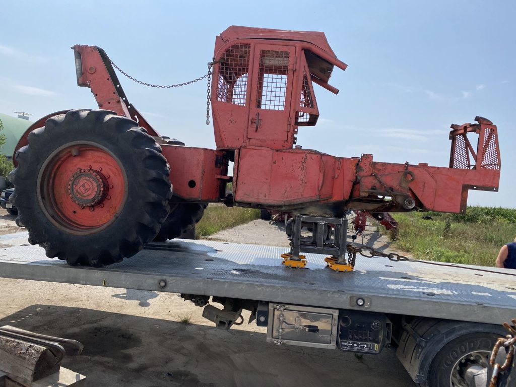
Such approach has not only increased safety during loading, and prevented additional damages to the machine. But, also it has made easier for us to remove the walking beam in the shop in Lucan. With the front end of the machine chained to the back of the unit, we have prohibited additional damages to the structure. Most importantly, however, with walking beam removed and the dolly support under machine, we have got a comfortable access to all cracks located in the front. The front dolly utilization has also allowed us to relocate the unit to a different location in shop. And, at the end the dolly has allowed loading the unit to haul it back to customer.
I highly recommend using dollies for such operations that involve multiple tasks.
In my opinion, the precise tracing of cracks and their analysis are paramount for successful repair and long utilization of unit after the repair. As we follow good trade practices, our work on Timberjack skidder has started with painting the cracks. Certainly, the experience helps a lot in this process but even novice with analytical thinking can manage this process successfully. Tracing of cracks begins a detective work of mechanical engineering related to damages. If you would like to know more about click here.
The process should start with marking with a contrast paint the location and shape of cracks to develop a a general idea where the damages are most severe. Marking the cracks shape also allows to identify resistance planes’ locations and resistance points’ locations. Usually, these are thicker parts of frame (ribbing) or thicker parts of wall. Obviously, we cannot identify small cracks at this approach but we can identify the shape and direction of large cracks and also direction of small cracks.
It is worth mentioning that the frame of out Timberjack skidder is not a uniform material. It consists of two plates: internal plate and external plate. The manufacturer has welded the external plate to the internal plate to increase the resistance to the fatigue damages. Both plates are 3/8 thick forming a composite weldment that is 3/4″ thick.
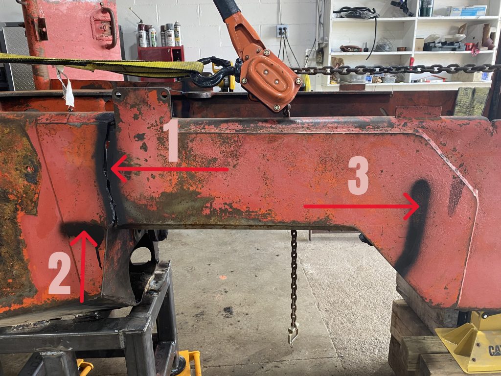
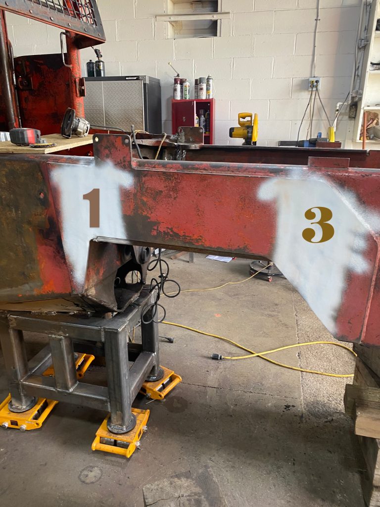
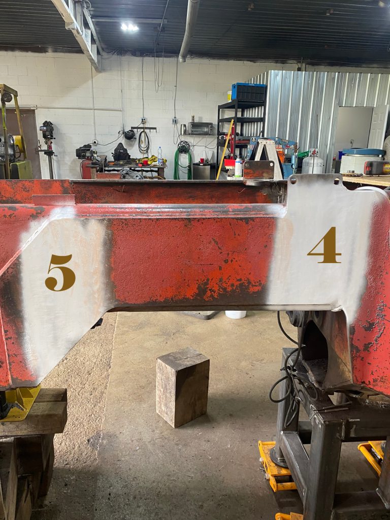
Cracks 1, 2 and 3 are located on the right side of the machine. Additionally, on the left side we have cracks 4 and 5.
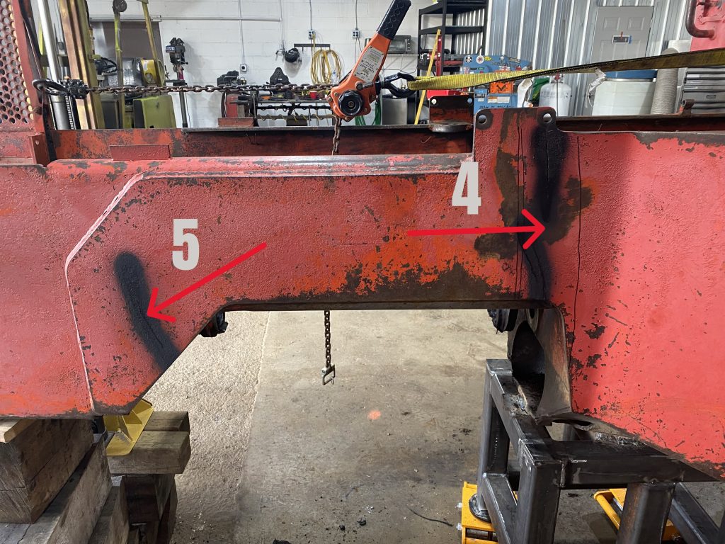
Cracks 1 and 3 are located on the right side of the machine and cracks 4, 5 and 6 are located on the left side.
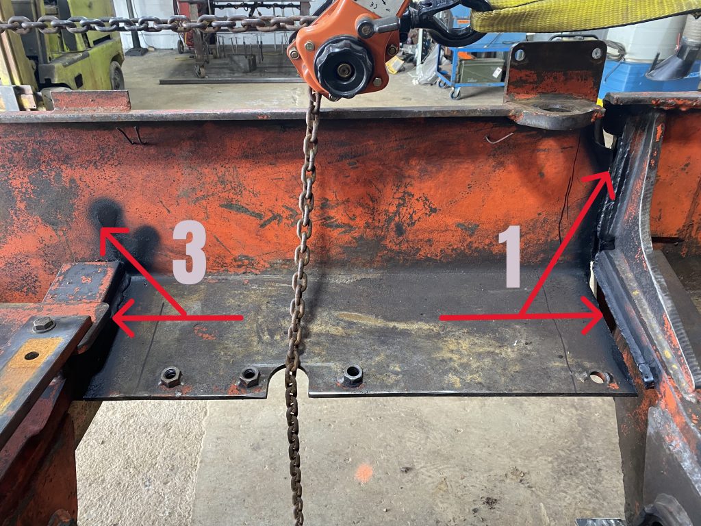
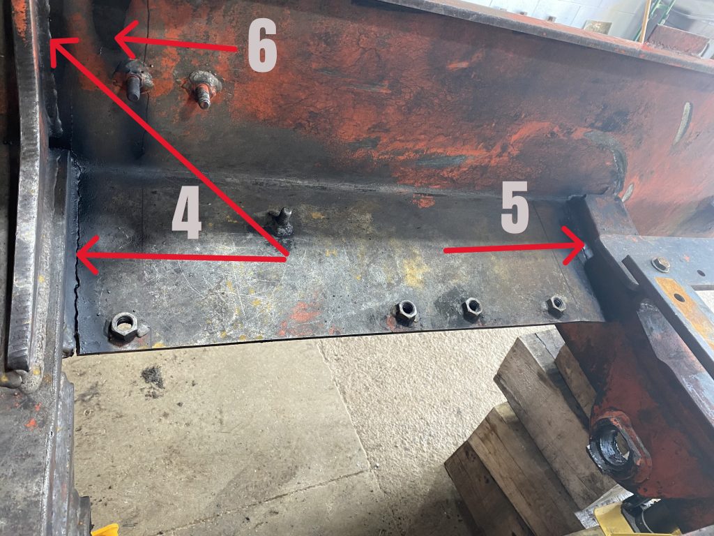
Cracks 3 and 1 marked with black paint as they are visible from inside of the skidder’s frame of the right hand side of the machine. And, cracks 4, 5 and 6 as they are visible from inside frame on the left side of skidder.
All cracks are material cracks and there is no weld cracks. Therefore we can conclude that these welds have formed significant resistance points to fatigue’s stress. The inside plate’s material cracks affect the area under the weld and then they follow the direction of the weld. There is a minimal branching off from major crack root with the vertical crack 4 being the exception.
Please keep in mind that we have only vertical external plates on this skidder, but internal plate is bent into vertical section and horizontal section.
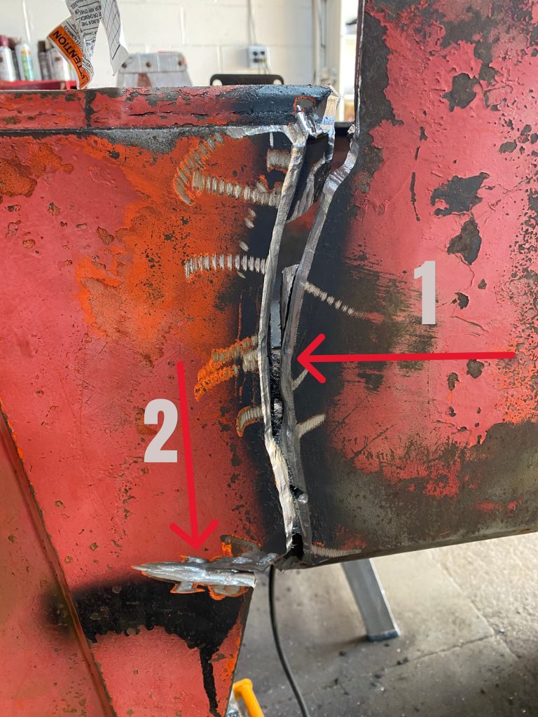
After painting cracks on the right side of our Timberjack skidder we can clearly see that crack # 1 although penetrated two plates it has deflected to the right. It has avoided resistance plane formed by inside frame ribbing. This is an excellent news since the main elements of the machine’s structure are still in good shape.
Crack # 2 although going across the plane of resistance has only penetrated the outside plate. Therefore, this crack has not affected the frame ribbing. Looking to the right, the crack 3 is clearly deflecting to the left. And, although it has initially penetrated two plates but it has missed the structural ribbing and then it hasn’t penetrated to the top.
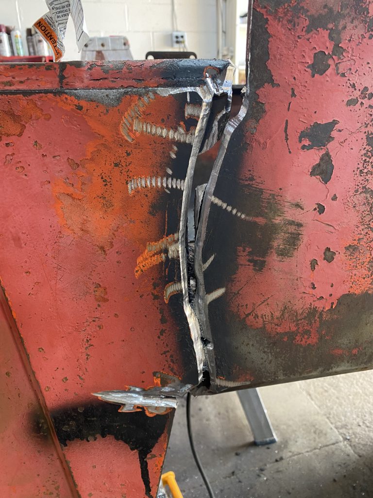
After dipper investigation we have concluded that crack 4 in external plate consist of 2 cracks, bottom and top. The distance between these 2 cracks is about 2 inches on this Timberjack skidder. As strange as it sounds, we can conclude that whole front of this skidder hangs on 2 inches of heavily fatigue plate that is 3/8 thick. This is unbelievable!!!
Crack 5 clearly bents away from the resistance plane formed by the rib and then meets the resistance point and stops.
Crack 1 is a clear and clean cut with undamaged welds in both vertical and horizontal plates. Crack 3 consists of horizontal portion and vertical portion. The horizontal portion is a clean cut but the vertical portion of crack 3 avoids resistance plane formed by the rib and tries to go around it but it meets resistance point.
When looking on the left side of the machine crack # 4 has developed multiple branches in the inside plate. One of the branches has penetrated to the top. Additionally, we have found crack #6 close to the mounting bolts that has penetrated this plate but it hasn’t penetrated the external plate. This crack is going down for about 5″. The shape of cracks 4 and 6 indicate multiple resistance points and resistance plane of the skidder’s rib. They also signal lower amplitude impact on the material.
Crack 5 has penetrated the outside plate and has stopped at the rib. Then it has penetrated the bottom portion of the bottom plate. We have noted that crack # 5 looks rather strange in horizontal plate due to lack of penetration of the vertical plate, severe rubbing mark, and bent horizontal plate.
This analysis of cracks summary will lay the foundation for “fishplating” thickness its size and shape. Additionally, we should develop point of view for welding joints, and fishplate joint preparation.
The Crack 1 and crack 4 located close to the skidder’s structural rib cause the main damage. However, Crack 1 is a main reason for all damages on this skidder.
The persistent impacting have caused fatigue material damage resulting in almost clean share of double plate. The cracks 3 and 5 are the consequential first order followers due to loss of rigidity caused by crack 1 and crack 4. The structural disintegration in other areas have caused crack 2 and 6 that are second order followers.
We have decided to place 8 fishplates on this Timberjack skidder. We want to place 4 fishplates on the external plates from outside to strengthen the vertical walls. Moreover, we want to place 4 fishplates on the horizontal potion of the cracks to strengthen the horizontal walls of engine compartment. The horizontal fishplates will go inside the frame since there is enough space there and they will not obstruct other mechanical components.
The fishplate thickness in vertical areas of double plating should be thicker than 3/8 but thinner than 3/4. Therefore, 1/2″ plate would be sufficient. The 3/8 fillet weld with higher tensile rod should be sufficient to attach these plates. The width of these plates should be enough to cover about 2.5″ of the rib area and then extend for more than 3 inches into damaged material. These fishplates should follow the shape of the top plate and stay at least 1″ off its edge.
In horizontal areas of single plate, the 3/8″ fishplate should be enough with double V irregular preparation close to rib and vertical surface for close surface matching. The welder should generate a modified weld on top of repair weld close to the rib consisting with vertical 1/2″ height and and then beveled weld. The welder should apply the similar weld characteristic to edge closed to vertical wall. The two other edges of fish plate should feature a 1/4 or slightly bigger filet weld. The fishplate located in horizontal portion of Crack 1 and Crack 4 should pass the first hole therefore 4″ width should be sufficient. Of course, we should drill holes in these fishplates to accommodate the corresponding bolts.
The proper grooving eliminates the crack from the material but only very experienced worker can accomplish this task successfully. During grooving the worker must remove the material to the left of the crack and to the right of the crack with the root of the crack located in the middle. And this is very difficult to achieve. Working with the pencil grinder and hand grinder this process is very tiring. It is very easy to miss a new branch of crack or even skip the root. It is very common for less experienced worker to position the root of the crack on one side of the groove resulting in leaving the crack in the body of material. Therefore, the welder should inspect the groove pattern prior welding it.
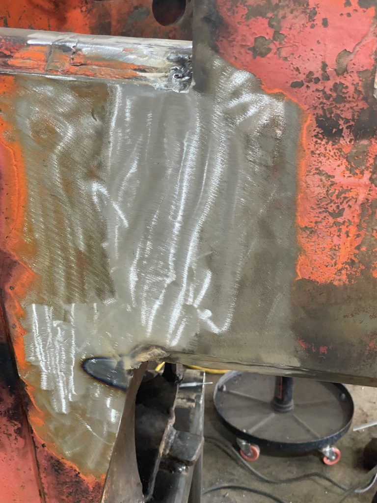
The worker has beveled all cracks on vertical double plates. He beveled cracks in outside plate and he beveled cracks in the inside plate. Therefore, we have created double V preparation on composite weldment. Additionally, he grooved all cracks that has not penetrated 2 plates. We have grooved all cracks on vertical surfaces that has stopped penetrating such as Crack 3, 2, 5 and 6. Grooving has passed the end of the crack by 1″ and has formed the landing.
Most importantly, he has beveled all horizontal cracks in single plate from the bottom up. Therefore, we have created the upside down V there.
As visible on the image below, the structural disintegration has caused a complete separation of structure in area of crack # 1. Therefore, the front area on the right side was sagging by about 1 3/4″. Fortunately, the top surface along the frame have allowed us to place a straight strong bar. We usually use HSTS 0.250×2″x2″ for this purpose. With large and heavy duty Bessey clamps and a 2 jacks the alignment went relatively easy.
Please note, we have beveled the Crack #1 from inside and outside prior alignment. The worker has cleaned the root from minor imperfection and he left the major curves intact.
The repair welds weld the crack up and then they can be capped or grinded flash and cover with fishplates. Most repair welds are modified welds with unregular shapes.
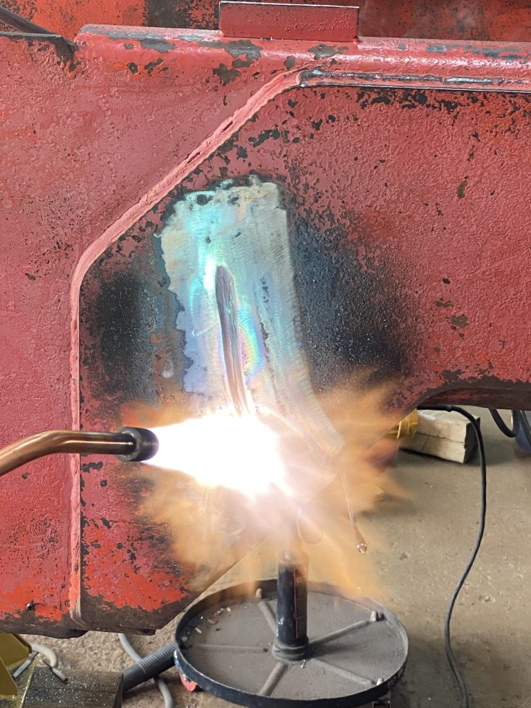
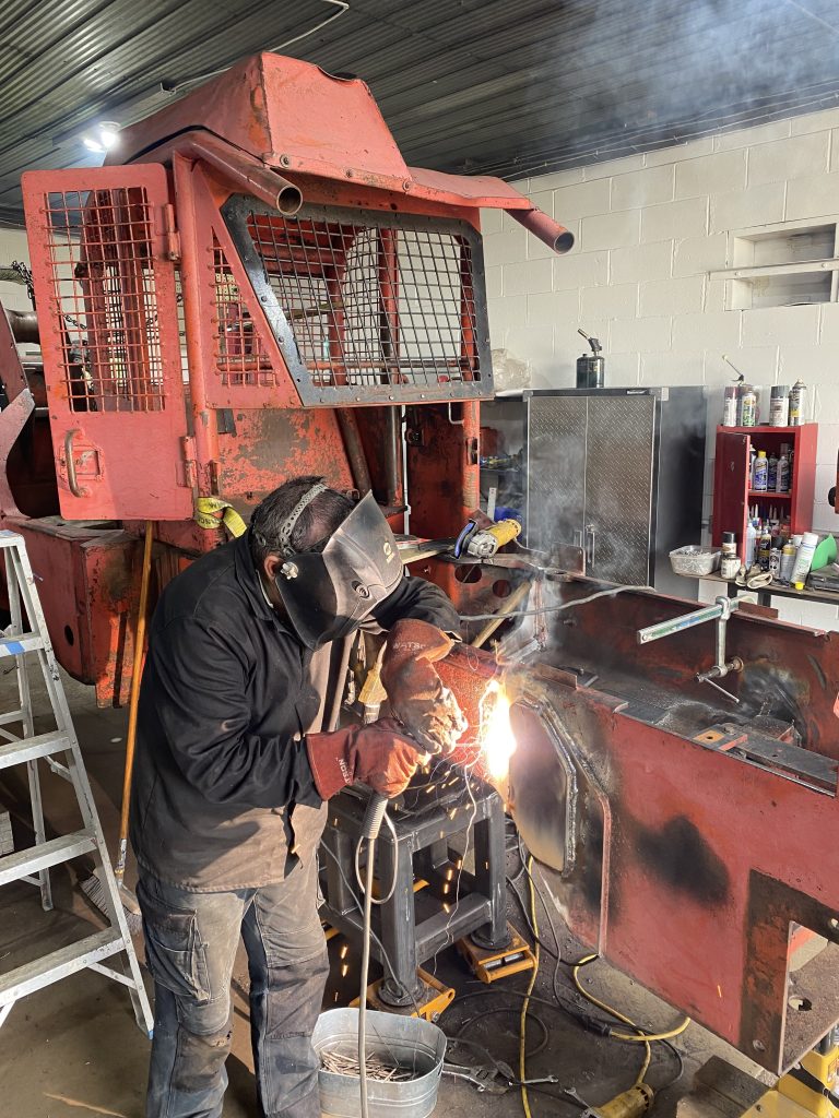
JW Portable Welding and Repairs uses welding in constant temperature method for welding all repair welds. This method allows for placement of long and large welds at the same temperature. Therefore, we weld the root pass and all following passes at the same temperature. Sometimes, to create one weld the welder uses more than dozen of welding rods and the creation of this weld can take more than 30 minutes, but still we maintain the same temperature in the whole process. The temperature levels and the monitoring system is our trade secret.
We use welding at constant temperature due to following reasons:
We weld all repair welds with high tensile rods of different parameters reflecting impact and vibration forces acting upon the joint.
First, we have completely welded grooved and beveled cracks on outside plates of vertical surfaces. Obviously, we have started with crack 1, then we went to crack 5, next was crack 4 and finally we have finished with crack 3. We have rotated sides due to the extensive heat. In this way, we have achieved also slow cooling pattern. After we have finished the welding, and the welds have cooled down we have grinded off caps of these welds flash in order to test them with in house MPT and then cover them with fishplates.
Next, we have welded all inside vertical grooved cracks at the constant temperature setting that was slightly different than the previous setting. Of course, we have removed all old filet vertical welds between the rib structure and the vertical plate, Therefore, the size of the weld have increased to 1/2″ on the rib side and extended 1/4″ passing the crack on the plate side. Please note, we have not intended to fishplate the inside welds on vertical side.
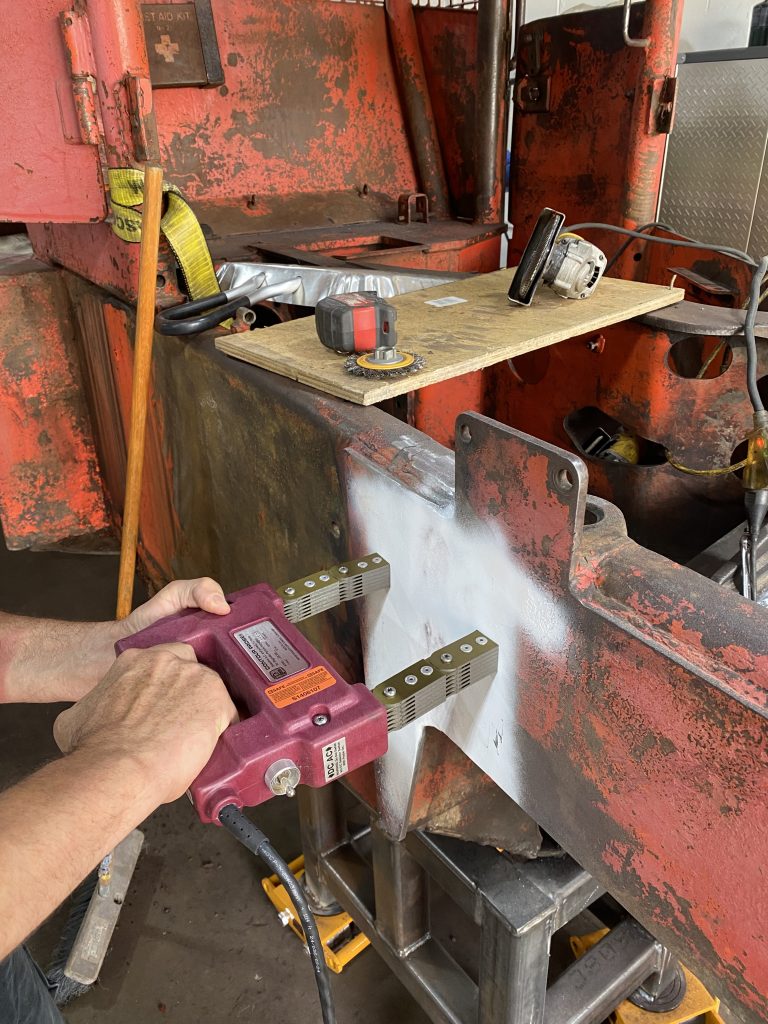
Next we have cleaned and modeled these welds for in house MPT testing
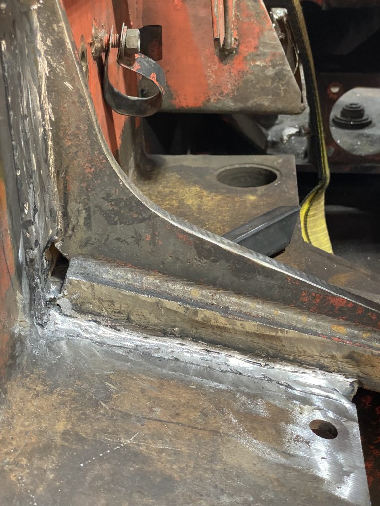
We have welded the caps on upside down V grooves on horizontal plates. Once, we have confirmed the penetration of these welds when looking at these V grooves laying on the floor and looking up, then we have placed large modified welds on top of caps welds that were joining the horizontal plate with the rib structure. Again, these welds were 3/8″ on the rib side and pass the crack by 1/4″.
Next, we have cleaned and modeled these welds for in house MPT testing.
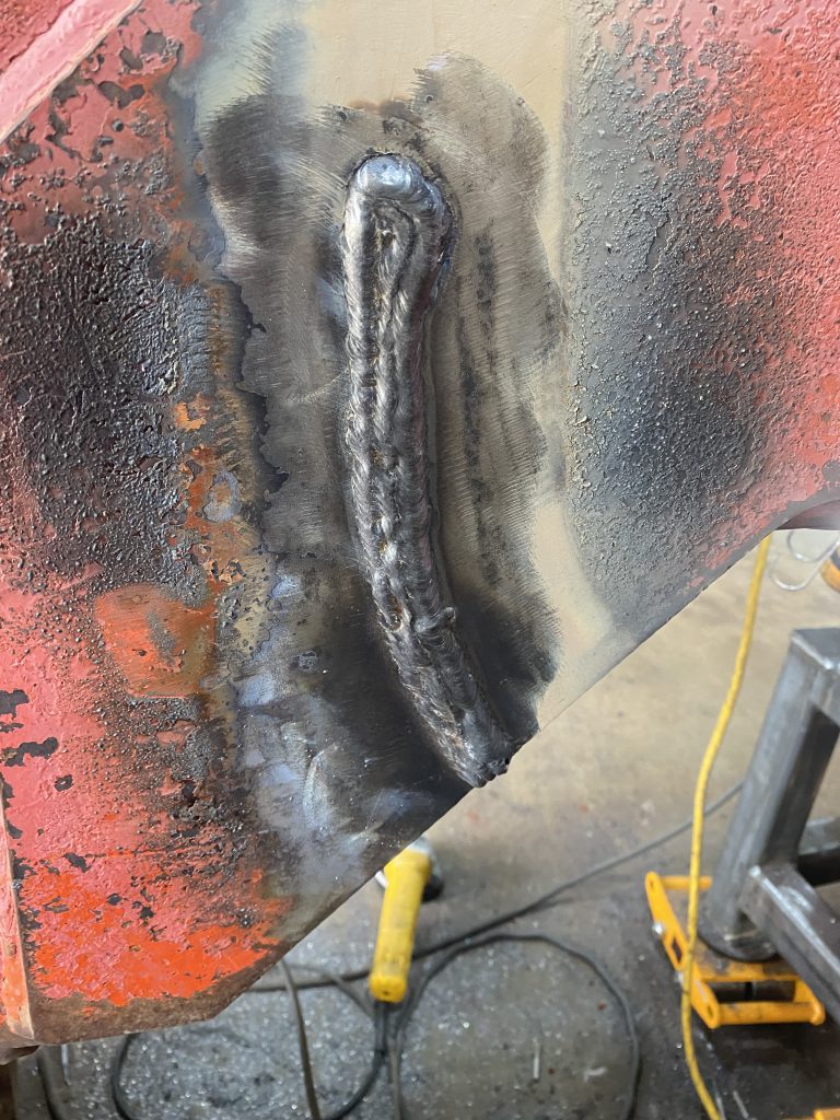
We have welded the upside down V grooves while laying down on the floor. And then we have placed a large cap on these welds since this side will not be fishplated.
It is worth mentioning, that during the preheat to our constant level, we have noticed another branch crack coming from crack 5 and going under the rib in bent plate. Therefore, we had to stop the whole process and groove this crack. Once we have finished grooving, we have welded the whole crack up with the large cap.
Next, we have cleaned and modeled these welds for in house MPT testing.
Our in house MPT is very important to us. The MPT testing provides the feedback to the whole repair process in following :
In case of our Timberjack skidder all of welds pass the in house MPT test except weld on Crack # 5. This crack was located at the edge of the weld and continue for about 1 1/2″. The crack was probably caused by our straightening plate effort that resulted in cracking the tack under the impact of 5 lbs hammer. Consequently, we had to groove this crack then weld it and tested again.
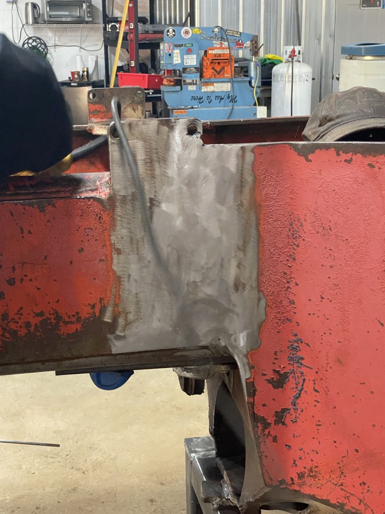
After all repair welds have passed MPT testing and with no additional cracks discovered, we have cleaned the contrast paint. Now, we were ready for fishplating.
We always weld fishplates in constant regime temperature since in this way we avoid temperature differential between the fishplate and the weld. In this way we reduce the stress acting on welds laying on opposite side of the fishplate. In case of thicker fishplates and thicker materials we also could opt into stress released welds.
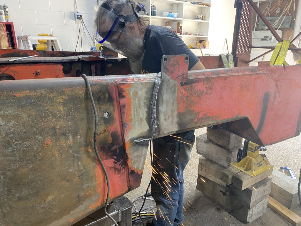
Since we have designed our fishplates in earlier stage, we’ve had them on hand. We have also prepared the surfaces for placement of these fishplates very well. Using our Bessey heavy duty clamps we have brought the fishplates to the touch with the base material. Then we have tacked them all.

Welding of these fishplates has been uneventful except the heat radiating to the welder due to constant temperature regime. These relatively large plates were radiating very significant amount of heat heating the welder in face and chest. With temperatures outside of shop close to 38 degrees cooling welder’s body was a problem. Next time, we will need to improve PPE for the welder facing such conditions.
Testing with in house MPT have not reveled any cracks.
The walking beam of our skidder has got also a few minor cracks. Some unexperienced welder has tried to fix them with substandard welding rod. We had to remove all these substandard welds and replaced them with our welds.
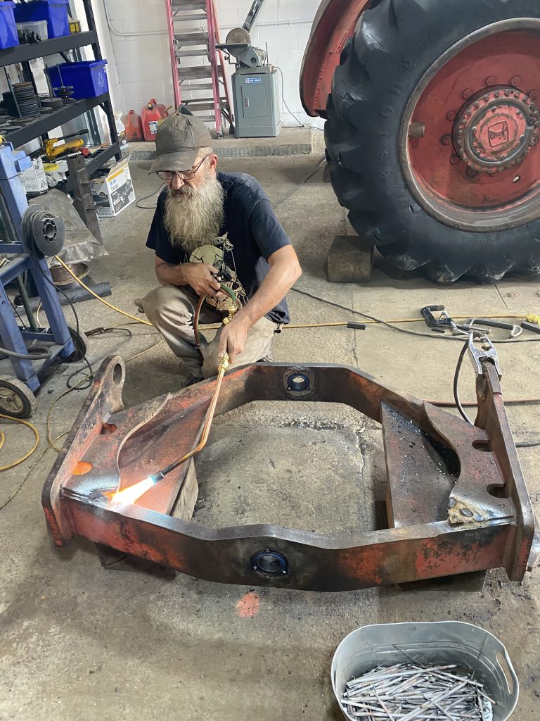
Additionally, we have replaced the bushing in the walking beam and then we have installed the walking beam using new pins.