

The railway crane welding and locomotive repair welding has challenged our welder’s skills, endurance, flexibility and engineering knowledge. Therefore, we have placed this project on our flagship project list for 2024. We are well known for welding on heavy equipment that involves welding on heavy plates. Most of the projects in this category are placed in well controlled welding environment in our shop in Lucan. Clients also opt to invite us to their well-organized shops to weld on their heavy equipment. We have accomplished many of such projects using our mobile welding services. However, welding on heavy equipment such as a locomotive and frame of the crane in the open field was definitely one of more challenging projects run by our company.
The railway crane welding project has included 3 smaller subprojects such as: welding the cracks on crane’s grapple, welding the cracks on crane wheels’ side frames, and some auxiliary welding on the railway carts. The locomotive repair included welding the crack in locomotive bumper. The large crack in the locomotive bumper was the most challenging from all other projects. But, lets go step by step through the railway crane welding to give you a more detailed image of our efforts.
You can contact us and send multiple images of your damaged railway equipment or damages to other heavy equipment. You can also text us or send videos on the phone number provided there. After we do an excellent job, please leave the 5 stars review of our service. Our specialized mobile welding unit or specialized welding shop will manage the repair under one roof.
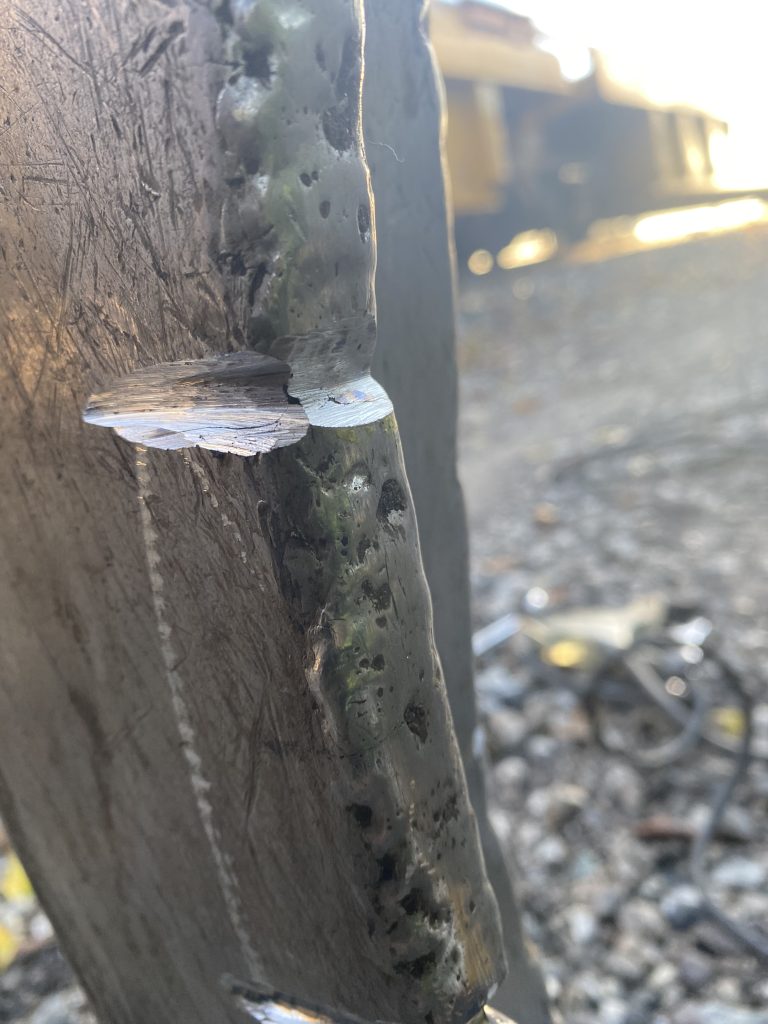
The railway crane’s grapple has been previously welded by other company with the short SMAW bits of surfacing rod going perpendicular to the grapple’s arm edge. Therefore they have not only covered the edge but also both sides of the edge. The idea of going across the edge have taken into account decreasing risks of possible heat cracks and grapple arm bent. But, this procedure did not eliminate inclusions. The length of the bit was about 1.5″ and it contained inclusions at beginning and at the end. These inclusions were the source for the cracks penetrating the arms.
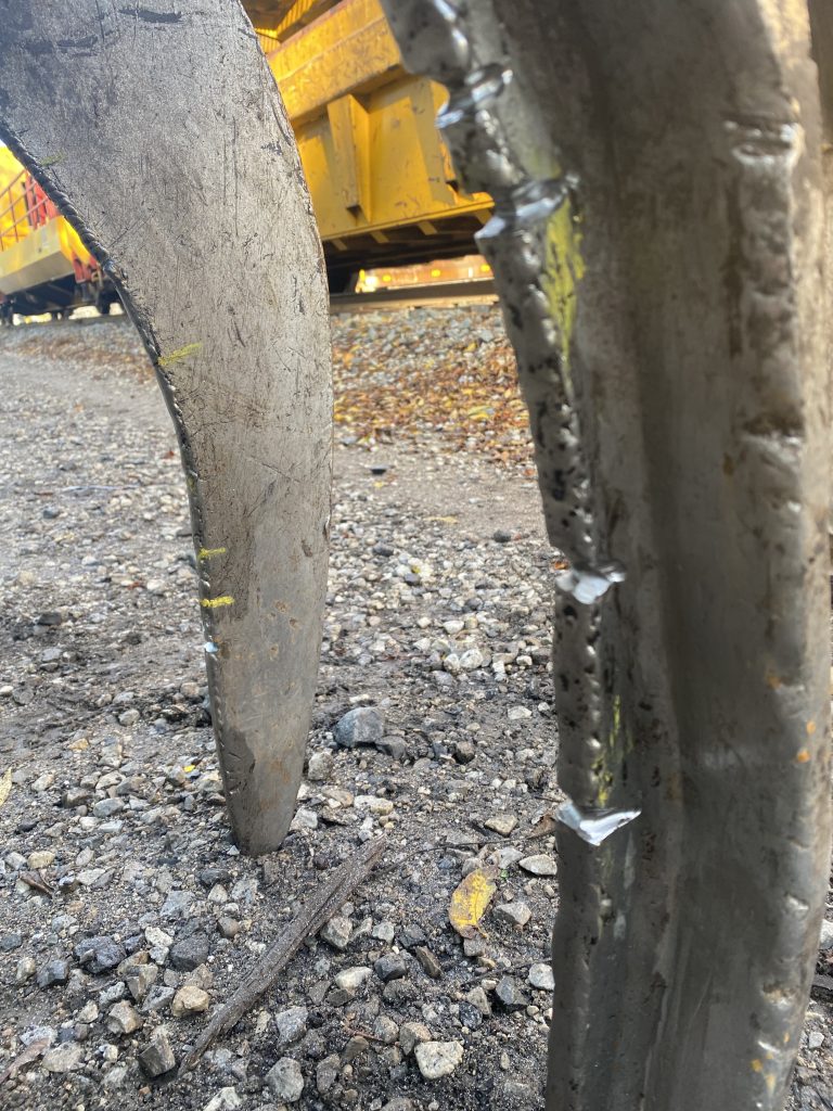
This time however, our goal was to repair the existing cracks in an urgent way. We have welded them with SMAW using preheat and high tensile rods as the surfacing rods do not fix cracks. This was rather emergency repair procedure.
The operator has told us that grapple went through the complete reconditioning in southern states with the Mexican welder doing the welding. Obviously this welder have used the wrong welding technique to do these welds. First, instead of SMAW, the GMAW is more practical along with any heat disperse technology. Or in fact with combination of technologies to avoid warpage of grapple arms. A premium hard surfacing wire would provide the much better protection against abrasive forces. Also longer bits going along the lengths instead of across the lengths of the arms are much better for inclusion elimination. Such surfacing welds would cover the surface more accurately with no inclusion. Since we offer GMAW surfacing welds for earth moving equipment and water drillers we know how these quality welds improve resistance to abrasion.
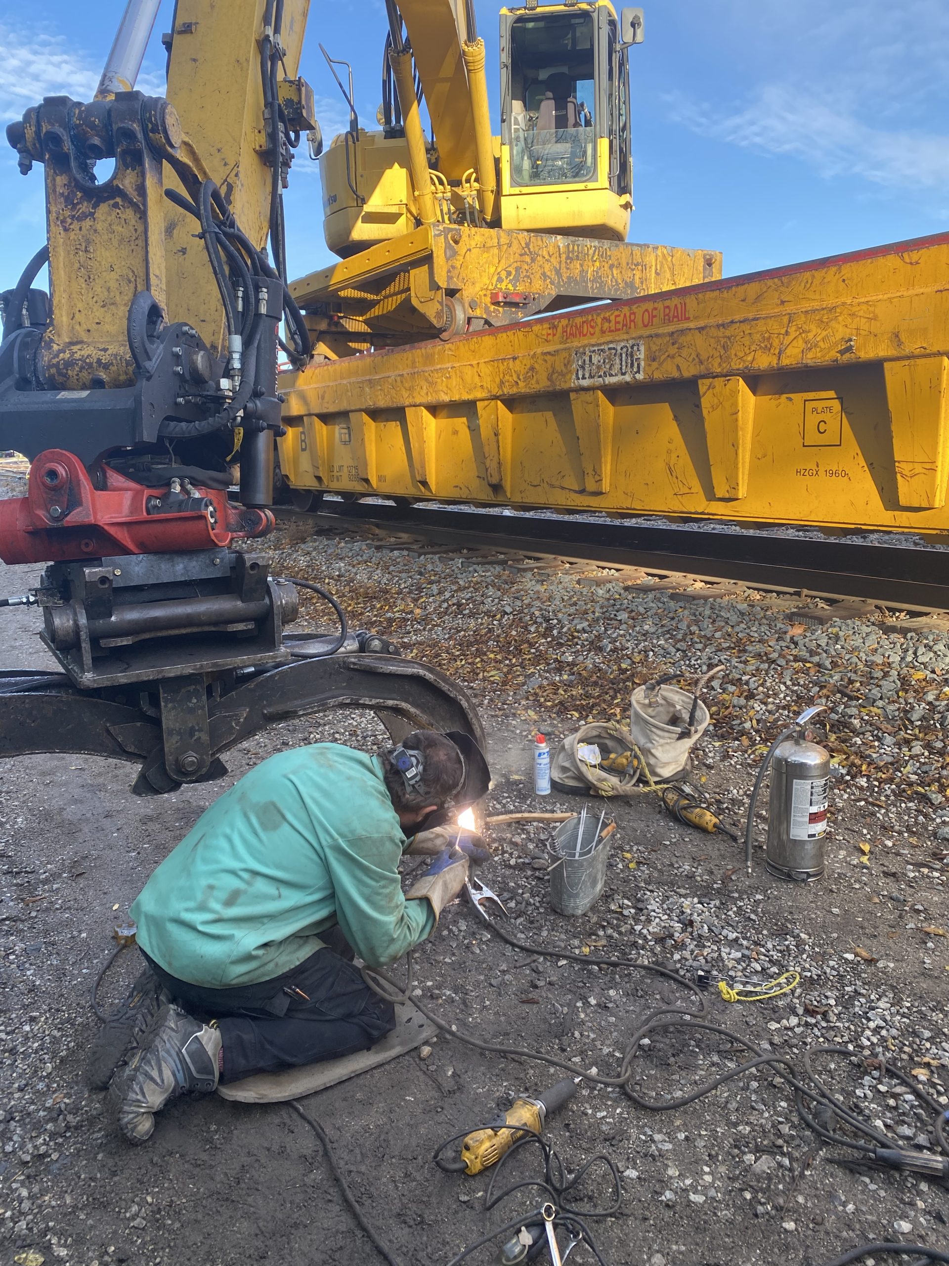
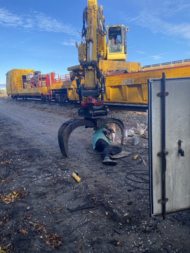
Inspection of railway crane from the bottom view was a lesson in human ingenuity and skill. We were very impressed with engineering of the whole crane. And crane’s ability to ride on top of the railway carts. Also the operator has impressed us with his skills and knowledge of the equipment. His explanations have helped us to understand the significant loads sustained by the railway crane during removal of rails.
Clearly, we could see the impact of these loads in the form of the cracks. Here is the weld repair of cracks on the left wheel’s side frame. Apparently, this was the most damaged wheel. As usual, we have used the high tensile rods for this repair.
Unfortunately, there wasn’t any space for placement some angular fishplate close to the locking pin. That is why we have placed 1/2″ large weld there. Then we have welded the smaller cracks and placed the fishplates in two planes, one in horizontal plane and one in vertical plane. These fishplates will prohibit spreading the crack.
The right wheel’s side frame repair wasn’t as bad as the left wheel. The cracks were smaller and I would say more gentle. Here is how we have managed this repair.
As mentioned above, the locomotive repair challenge was to weld crack on locomotive bumper has left me with a long lasting impression that I will remember for years. This was a very difficult weld on heavy wall locomotive bumper. The weld difficulty included technical aspect, extremely difficult welding position and almost confined space with only one hand reaching the spot. That is why this project has landed on the flagship list in 2024.
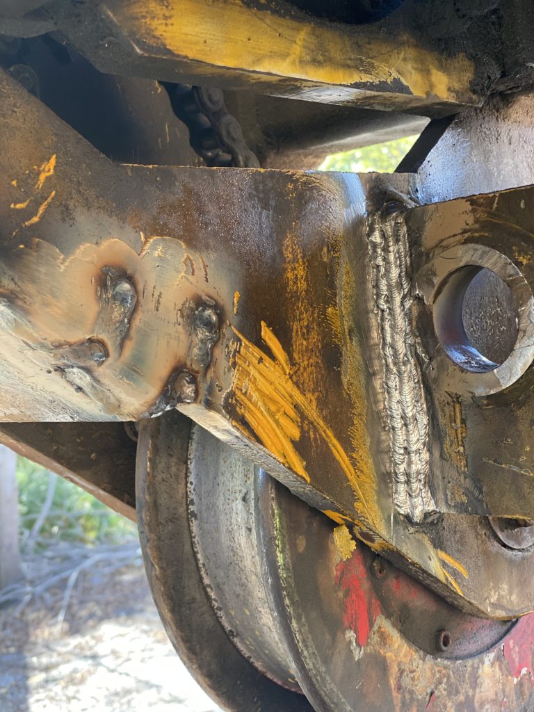
The thickness of the bended plates are about 1″ to 1 1/2″ and the crack has penetrated through the thickness of the plate due to severe material fatigue caused by locomotive impact when pulling and pushing the heavy load. Additionally, the engineering failure have contributed to the development of this crack due to creation of relatively weak spot.
Here is the grooved crack as visible from the under locomotive bumper when laying on the railway tracks.
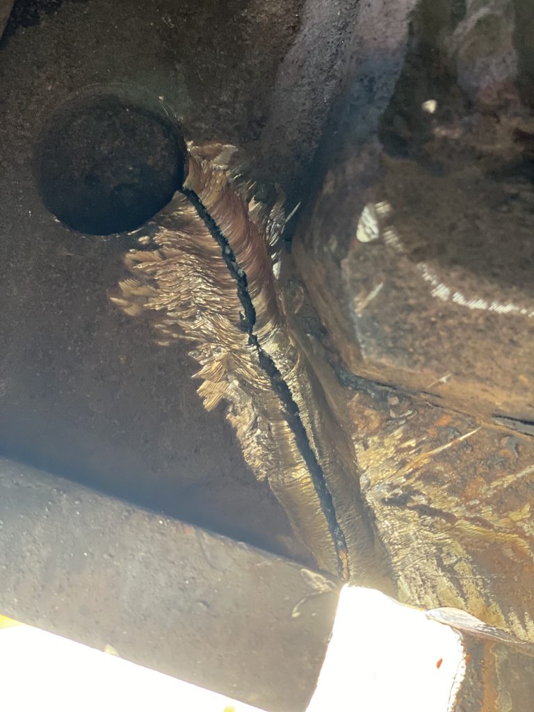
The welding of this crack had to take place from under the locomotive and from outside, while standing in comfortable position. The thickness of the plate and the lack of space didn’t allow for a traditional V groove. That is why we have used a double V groove. We have grooved the crack laying down on the railway tracks and then we have grooved the same crack when standing comfortably outside. Therefore, we had to generate two welds to fix this crack, one weld when laying on the railway tracks and one when welding outside in comfortable position.
Since we always try to push the envelope a little bit more, we have tried to improve the strength of this weak spot created by the edge of the bumper’s frame and the large vertical weld that is the part of locomotive structure. The welding laying on the railway tracks and material joint composition was not too favorable to create any improvements from this position. That is why, we have decided to do these improvements from the outside when standing comfortable close to locomotive.
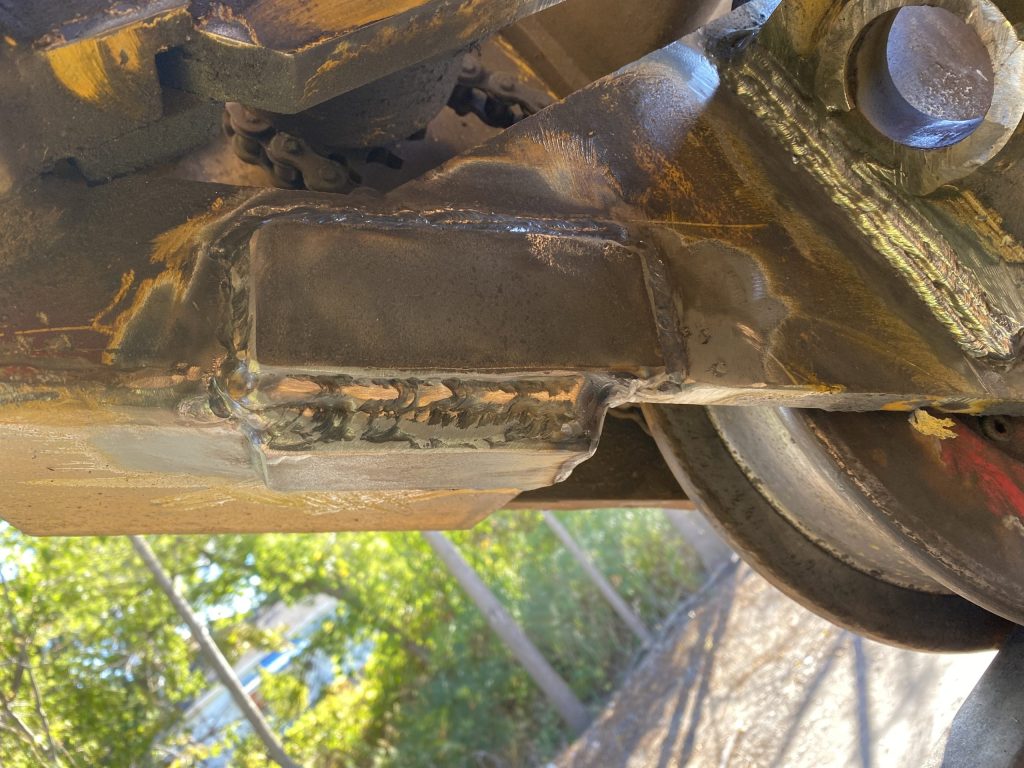
Here is the weld from inside after the pre – heat. The bottom of this multi -pass weld is in vertical plane but the top is on the running away from the welder plane.
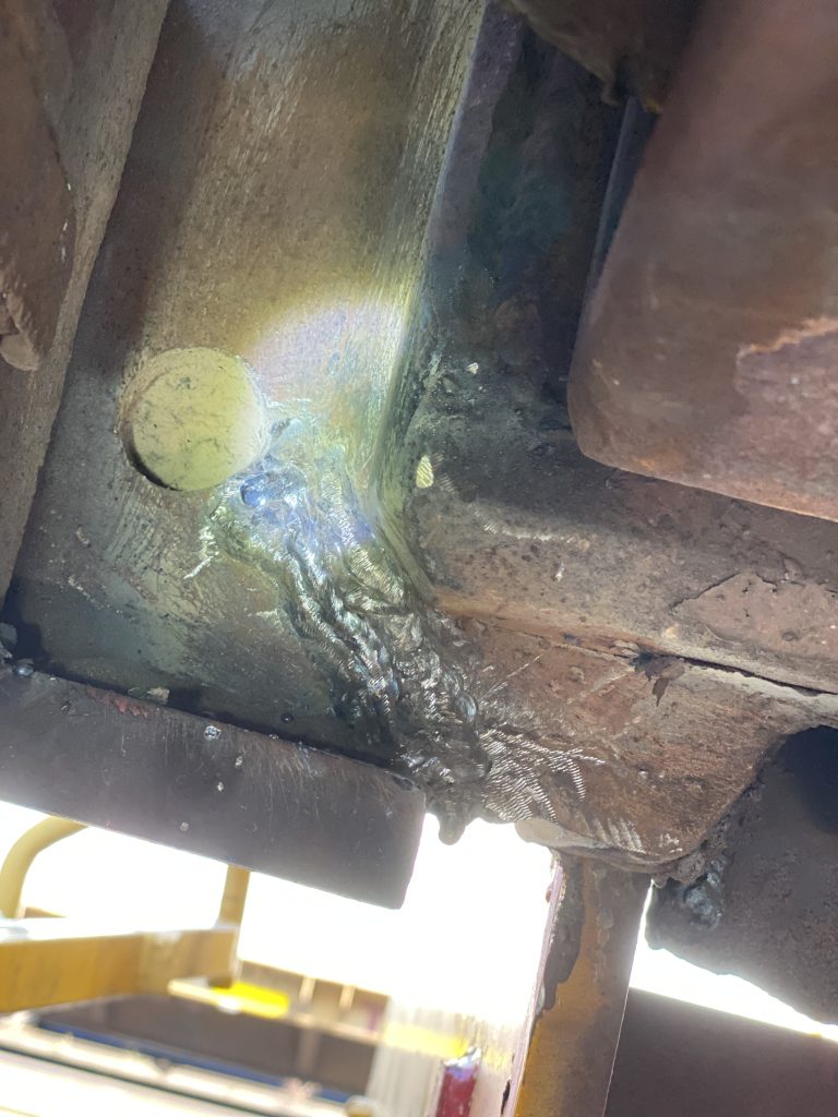
The welder has welded the bottom portion of the weld, the vertical portion when laying down on railway tracks. The upper portion of the weld on the running away plane, the welder has welded in sitting position and helmet squished into cavity in locomotive deck. With one eye seeing what is going on and one hand reaching the spot, the welder has welded the upper portion of this multi – pass weld.
Welding the crack from outside was obviously less challenging for the welder. The welder could find a comfortable position with perfect visibility and distance from the crack. Also, the preheat could take place in more controllable environment. That is why we have chosen this side to improve the weakest spot during this locomotive repair.
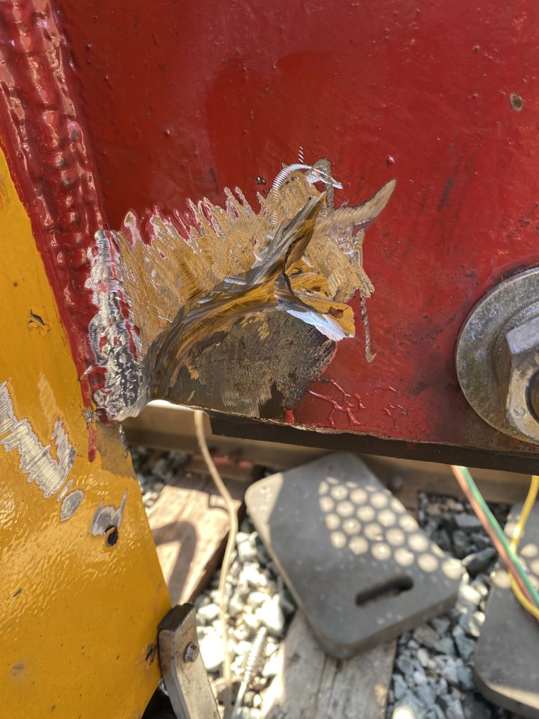
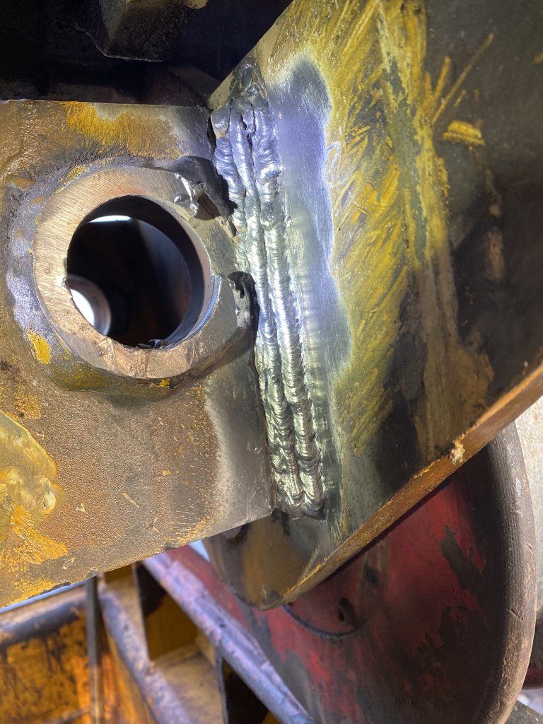
As you can see the grooving follows the crack and exposes the bore. Obviously, the weakest spot is at the bottom very close to the right side of the right multi – pass vertical weld. This is the spot where the crack begins and this is the spot that we have needed to improve.
The vertical multi- pass weld is about 3/4 ” filet weld. Therefore, the idea was to widen this filet weld to extend it pass the beginning of bumper’s support frame. In this way we have attempted to relocate more impact stress on the bumper’s support frame structure.
While proposing this solution to the operator, we already knew that it will not resolve the problem completely, but it was the best solution in this rather urgent situation. We have also realized that the manufacturer of this locomotive should be aware of this engineering failure in order to provide the long term remedy to this locomotive and to implement a better solution when producing a next locomotive.
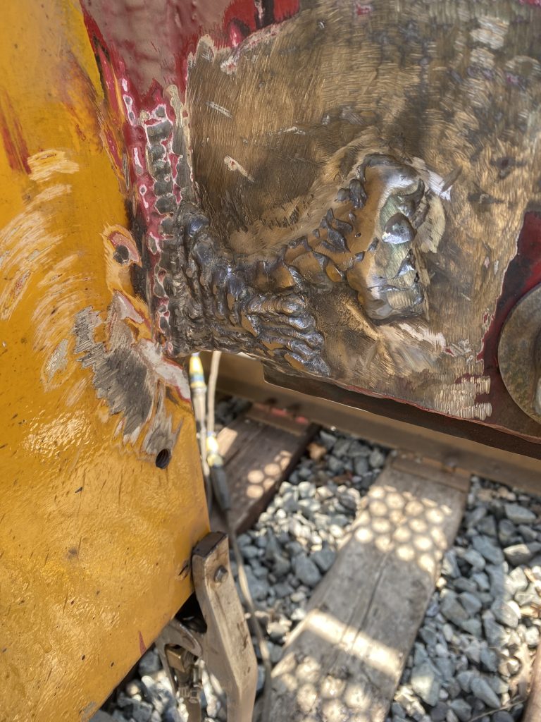
After the preheat, the welder first has welded the crack shown above with a special attention to weld the cap of the weld repair a pass wider than necessary. Additionally, the width of the cap weld was slightly increased at the bore location.
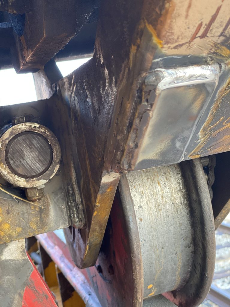
Then the welder have placed a L shape weld to increase the strength of the structural vertical weld at its bottom. Finally, the welder have placed a multi pass horizontal weld in the letter L to directly move the stress to the structure of the bumper. The end of this multi- pass weld extends the edge of the structural frame support of the bumper by about 1.5″
The full documentation of this locomotive repair including detailed images and welding procedures has been sent to the manufacturer of this locomotive.